I started with a simple scene that has several cylinders, a ground plane, and a background card, simulating a forest scene or something.
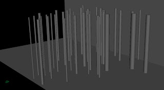
The difference with height and depth compositing versus standard depth compositing is for scenes that have a lot of tall objects that break the top of the frame, such as a foggy forest scene. If your scene has a low horizon or shows a lot of sky, then the effects of the height pass will not be too noticeable and a simple depth pass will work just fine. The method outlined here will work just fine for an anti-aliased depth pass. In the example here, we will also create an interactive light pass.
The first step is to create the shader. The basic principal here is that any image is made up of three channels, red, green, and blue, which are really 3 separate grayscale images combined to create the final image. In most cases, we focus on the result, but here, we need several different grayscale mattes, instead of rendering out multiple passes, we can render 3 in a single pass, using each channel as its own pass, we don't care about what they look like together, just what each component looks like.
For this example, the red channel will contain our interactive light pass, the green will contain the height information, and the blue channel will hold our depth pass. To get started, create a lambert shader and three ramps. Set the color of the lambert to black.
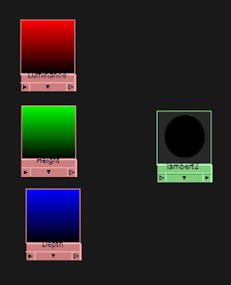
Set one ramp to go from black to red and name it Luminance, set another ramp from black to green and name it Height, and set the third ramp from black to blue and name it Depth. Be sure that all of the ramps are set to V Ramps.
Next create 4 locators, these will make it easier to set the bounds of the height and depth. They aren't necessary, but make it a lot easier to set up the height and depth. Name the locators Top, Bottom, Near, and Far.
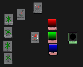
We will also need the following utilities, a sampler info node, surface luminance node, and a set range node.
Next we will set up the locators with the camera. First parent the Near and Far locators underneath the camera, then zero out the translation and rotation values on the locators. They should now be at the pivot point of the camera. The next thing to do is to point constrain the Top and Bottom locators to the Far locator. Be sure to only constrain the X and Z axes, so that they will always be above and below the far node, but they can be at any height.
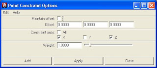
Maintain offset should be off. Lock the X and Y attributes from the Near and Far locators, and the X and Z attributes off of the Top and Bottom locators. Now the Near and Far should only be able to move to and from the camera, and the Top and Bottom up and down. We will use the Z values to determine the depth and the Y values to determine the height. We will take those values to drive the color of the ramps, we just need to remap to values to fit the 0 to 1 range.
Connect the translateY value of the Bottom locator to the oldMinY value of the setRange node. Then connect the translateY value of the Top to the oldMaxY.
For the depth, the important thing to remember is that the Z values are always negative in relationship to the camera, so the Far Z value will be a smaller number than the Near, so the Far should be mapped to the oldMinZ value and the Near to the oldMaxZ.
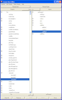
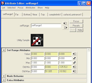
The Min and Max values should be 0 to 1, to remap them to the V range of the ramps. For the values, map the pointWorldY from the sampler info node to the valueY of the set range. Next, map the pointCameraZ of the sampler info node to the valueZ of the set range. Finally, map the outValue of the surface luminance node to the valueX of the set range.
Now to connect the ramps, map the outValueX to the vCoord of the Luminance ramp, the outValueY to the vCoord of the Height ramp, and the outValueZ to the vCoord of the Depth ramp.
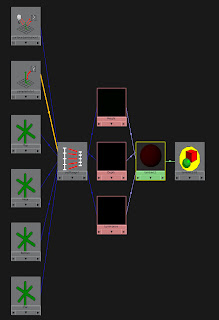
The final thing to do is to delete the 2dPlacementNodes of the three ramps. The oldMaxX value of the set range node is the cap for the surface luminance node. The surface luminance node measures surface brightness, but it is a float value that is higher than one.
In Part II, we will go over setting up the render and compositing the pass.


thx man i m trying but something goes wrong ..can u plz tell me the easy method
ReplyDeleteAwesome... HD_ShaderTutorial
ReplyDelete